Related Books


Books / Introduction to Computers and Operating Systems / Chapter 2
Process and thread management
The module explains how an operating system executes user applications and manages its functions in a form of a collection of processes. It will also describe the process, process states, process data and control information, and other related information. Moreover, the module describes the meaning of multithreading and the types of threads.
In this chapter
- What is a process?
- Process Control Block (PCB)
- Process State Model
- Operating system control tables
- Process Control Structures
- Modes of execution
- Process Creation and termination
- Processes and threads
- Types of threads
- User Level threads (ULTs)
- Kernel Level Threads (KLTs)
- Combined Multithreading Model
What is a process?
Multiple applications can run and share the computer resources simultaneously. In multitasking environments, the operating system switches among multiple applications in a fraction of a second, so that all applications can do progress at the same time. A process refers to an executing program. Most applications are made of sub-programs that can run independently as separate processes. Program code (AKA process trace) and data are the essential elements of a process. Process trace specifies the behavior of an individual process during execution. Both of these two elements may be shared with other processes. Therefore, multiple processes can be executing a whole or part of a single program or sharing some of its data.
Process Control Block (PCB)
When a program is running, it can be uniquely characterized by the following elements in addition to others:
We call the memory block that contains these elements Process Control Block (PCB). PCB contains the contextual process elements that can be used to resume process execution in case of interruption occurrence. If an interrupt happens, the operating system stores the process PCB and retrieves it back after handling the interrupt to resume the process execution. |
Process State Model
When a program is run by a user or system, one or more processes will be created based on the structure of this program. From the creation step to termination, the process passes through a number of states. We start up learning about process states through the 5-state model ([Figure 2]) which describes a process state at any time as either: new, ready, running, blocked (or waiting), and terminated.
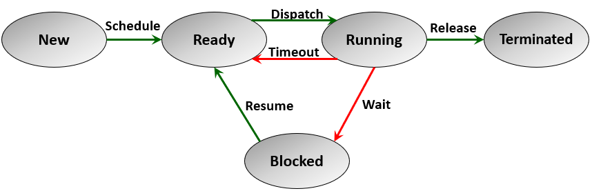
Figure 2- The 5-states model of a process execution
A new process needs to be admitted to memory using the operating system scheduler. The process then becomes in the ready queue and its state becomes ready. Process dispatcher is a system process that is responsible for switching between the running process. Then a ready process can take turn to be dispatched to run on the CPU until it terminates, or it completes the allocated time slice and then it moves again to the ready queue. If a process is waiting for an I/O event to occur its state becomes blocked or waiting. The process stays in the blocked state until its I/O events occur, then it becomes ready again.
Process suspension is another state that indicates removing the process temporarily from memory to allow scheduling another process of higher priority or to resolve some conflict of running processes and improve the processor utilization. [Figure 3] describes the 6-state model of a process which shows the suspended state. A blocked process can be suspended (i.e., swapped out of memory). The suspended process remains in the suspended queue until the operating system scheduler decides to activate it and put it in the ready queue.
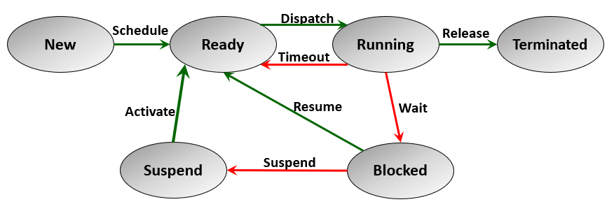
Figure 3 - Process 6-states model
Figure 3 does not provide the full picture of process suspension. The following figure ([Figure 4]) shows the 7-state process model which describes the complete process state model: new, ready, running, blocked (or waiting), blocked suspended, ready suspended, and terminated.
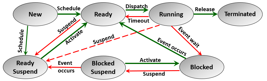
Figure 4 - The 7-states model of a process
Figure 4 distinguishes between two states of suspension: blocked suspended and ready suspended.
Operating system control tables
Operating systems constructs and maintain control tables to help manage processes and system resources. While the details of these tables differ from a system to the other, operating systems maintain four fundamental control tables for memory, I/O devices, files, and processes.
Memory tables help the operating system manage the main memory and virtual memory by tracking the following.
- Allocation of main memory and secondary memory to processes
- Information about the allocated and unallocated memory spaces
- Security and protection attributes of allocated process spaces
I/O Tables help operating systems manage the I/O resources and operations through the following.
- Tracking the available I/O devices and those assigned to processes
- Maintaining the statuses and monitoring the signs of progress of I/O operations
- Tracking the allocated buffers in the main memory for I/O transfer operations.
File Tables provide the operating system with the information required for secondary storage I/O virtual memory management. File tables help operating systems with the following:
- Supporting the file management system program and basic primitives.
- Maintaining information about the existence of a file, usage or I/O status, security and access attributes, and others.
- Allocating secondary storage space to files and maintaining file system schemes.
Process tables help operating systems manage process execution through the following.
- Maintaining process state queues e.g., ready, and suspended queues.
- Maintaining references to memory address space allocated to process
- Tracking I/O operations and files associated with processes.
Process Control Structures
Operating systems process control tables help manage process execution on a global scale by using data structures that are external to process themselves. operating systems also maintain a large amount of data specific to each process to help manage and control its execution. Process image includes all the control information specific to a process.
A process image includes the following information about a process.
-
Process trace: program code
-
Process data: program data
-
Process stack: code function call stack to store function return addresses and information
*- *Process control block**: Identification and control information.
Modes of execution
There are two modes of execution operating systems used to run code instructions of process traces: user mode and system mode. User mode is used to run high-level user functions such as image rendering and text editing. System mode is used for low-level system function that controls sensitive information or manage an I/O operation.
The following is a quick comparison between user and system modes of execution.
User mode
- The initial mode when a user starts to execute a program
- Runs high-level user functions
- Non-privileged mode
- The mode bit is set to 1
System mode
- Operating system switches to system mode to run sensitive program code or handles system functions
- Runs low-level system functions
- Privileged mode (AKA control mode, kernel mode, system mode, and supervisor mode)
- The mode bit is set to 0
Process Creation and termination
In operating systems, process creation takes place so frequently as the system runs. Many system-level processes are created with the machine startup. User programs create processes as they run on the system. Other processes are created with system services such as user login, remote control, timer, scheduled batch jobs, etc. When a process is created at first, it is assigned a unique number (process ID) by the system. It is also allocated a memory address space. Also, a PCB is created for the process and a program code is assigned to it. When it starts to run, a process image with all its components is created. A process is created by spawning it from a parent process. Thus, the processes created in the system at any point in time constitute a large tree structure called process tree (Linux example). The parent-child relationship among processes is usually described by resources sharing, execution, and user program options. Resource sharing options available to the spawned process are the following:
- A child shares all resources with its parent.
- A child shares only a subset of its parent’s resources.
- A child shares no resources with its parent.
Execution options available to the spawned process are the following:
- Both parent and child execute concurrently
- Parent waits until its child terminates then resumes its execution
User program choices for child process include the following:
- Child duplicates the parent program
- Child loads a different user program
When a process completes its jobs, it terminates execution by executing a Halt instruction. This instruction is usually included in the program code as the last sentence after completion. It is also triggered when a user decides to close an application or log off some operation. Process termination also occurs in numerous other situations. Examples of these situations include the following.
Up-normal activities, e.g.,
- Process exceeded specified time.
- Process requests memory space that is not available (such as, running an infinite loop)
Security aspects, e.g.,
- A process attempts to access unallocated memory space
- Data misuse and an unprivileged operation attempted by the process
Failure occurrence, e.g.,
- I/O failure (such as file not found, invalid I/O operation)
- Arithmetic error (such as divide by zero error)
Processes and threads
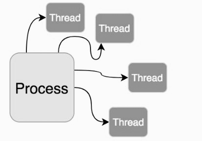
Multithreading is a process execution model in which the process is dispatched in multiple lightweight processes called (threads). Each thread can be executed independently, and it can share some or all the resources of a process. Depending on the system hardware, threads can run in parallel on multicore or multiprocessor systems and can run concurrently on a single processor by using the time-sharing mechanisms. Multithreading enriches operating systems by improving their performance and execution capabilities.
In operating systems, a process is the unit of resource ownership and protection, and a thread is a unit of dispatching. As an independent lightweight process, threads have accounting and control data related to them. Operating systems maintain Thread Control Block (TCB) for each thread. Also, each thread is assigned a user stack and a kernel stack space.
Depending on the type of threads, the life cycle of a thread goes through a number of states. For example, the Java thread life cycle can be new, runnable, blocked, waiting, timed waiting, terminated.
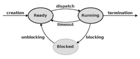
Figure 5 - Three-state model for thread execution
In most multithreading environments, three fundamental states are part of a thread life cycle: running, ready, and blocked as shown in Figure ]. Running means the thread is currently executing on the system CPU. Ready state means the thread is available to start the execution on the system CPU. Blocked threads are waiting for some I/O operation to complete before they can resume their execution.
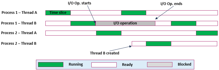
Figure 6 - Thread execution example
Figure 6 provides an example of thread execution on a uniprocessor environment. Each thread is allowed a time quantum and then another thread is selected for running. In the example, both processes 1 and 2 have 2 threads: A and B. At the start P1-TA is running until its allowed time is over, then P1-TB is pulled from the ready queue to execute. P1-TB requests I/O operation and then becomes blocked until it is completed, P2-TA then runs, and then P1-TA follows. Process 2 spawns thread B which then takes a turn to start running next to P1-TA.
Types of threads
Multithread designs include two types of threads in operating systems: user-level and kernel-level threads.
-
User Level Threads (ULTs) are part of the user application design and are implemented using multithreading libraries.
-
Kernel-level threads (KLTs) are lightweight units of kernel scheduling in which one or more threads exist within each process. In most contemporary systems, both types of threads exist separately at the same time. Therefore, a mapping between the ULTs and KLTs is applied differently in different operating systems.
User Level threads (ULTs)
User-level threads are created, terminated, and completely managed by their applications. The threads are created and handled by the application programmer by using multithreading library APIs. Multithreading libraries are mainly of two types: explicit and implicit multithreading.
Explicit threading
- Creation and management of user-level threads designed and implemented by the application programmers.
- Examples: Windows threads and Java threads.
Implicit threading
- Creation and management of user-level threads handled by compilers and run-time libraries rather than programmers.
- Examples: OpenMP library and Message Passing Interface (MPI) library.
Advantages of ULTs are the following
-
Thread scheduling can be completely controlled at the application level.
-
Switching between threads is done at the userspace level and it does not require the privileged mode of the operating system.
-
ULTs can simply run on any operating system complying with the multi-threaded application.
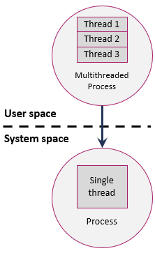
Since the operating system kernel does not recognize the ULTs inside a user process as shown in [Figure 7], ULTs have two disadvantages.
Disadvantages of ULTs:
-
If a ULT calls a system function that requires privileged mode, the system will block not only the thread but also all other threads in the same process.
-
A multithreaded application cannot take advantage of multiprocessor systems.
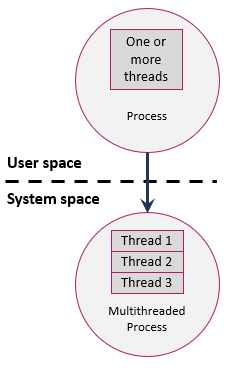
Kernel Level Threads (KLTs)
Kernel level threading is a feature supported by all contemporary general-purpose operating systems, e.g., Windows, Solaris, Linux, and macOS. In these systems, kernel-level threads are managed and scheduled by the operating system kernel. Applications run on these systems don’t need to implement any ULTs in the userspace. Therefore, a single thread process at the user space can run on multiple threads at the system level.
Advantages of KLTs are the following
-
Multiple threads can be simultaneously scheduled on multiple processors from the same user process.
-
Blocking of one thread in a process does not block the other threads of this process.
-
KLTs allow system levels functions to be multithreaded.
Disadvantages of KLTs:
- Switching between threads within the same process requires switching to privileged mode.
Combined Multithreading Model
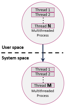
To utilize multi-processor machines, some operating systems (e.g., Sun Solaris) execute user-level threads on top of kernel-level threads through M: N mapping model (shown in [Figure 9]). In this multithreading model, multiple ULTs from a single process are mapped onto smaller or equal numbers of KLTs. Therefore, the types of thread mapping in this approach are the following.
Many-to-one mapping
Multiple ULTs are mapped onto a single KLT. This approach is equivalent to pure ULTs, if one thread is blocked all other process threads are blocked. Multiple ULTs cannot take advantage of multiprocessor or multicore systems.
One-to-one mapping
Each ULT is mapped to one KLT. This approach provides more concurrency in comparison to many-to-one and many-to-many mapping approaches. The one-to-one mapping is not always available, and it depends on the availability of KLTs in the system and the execution overheads. Example operating systems that allow this mapping are Windows and Linux, and most operating systems.
Many-to-many mapping
Since the number of system-level threads depends on the system design, it can sometimes be a restricted resource, and thus, a one-to-one mapping is not always available. Many-to-many mapping aims to distribute the number of ULTs over a smaller number of KLTs. Therefore, many-to-many mapping is better than many-to-one but less than one-to-one for its lower level of concurrency. Example operating systems that allow this mapping are old salaries versions.